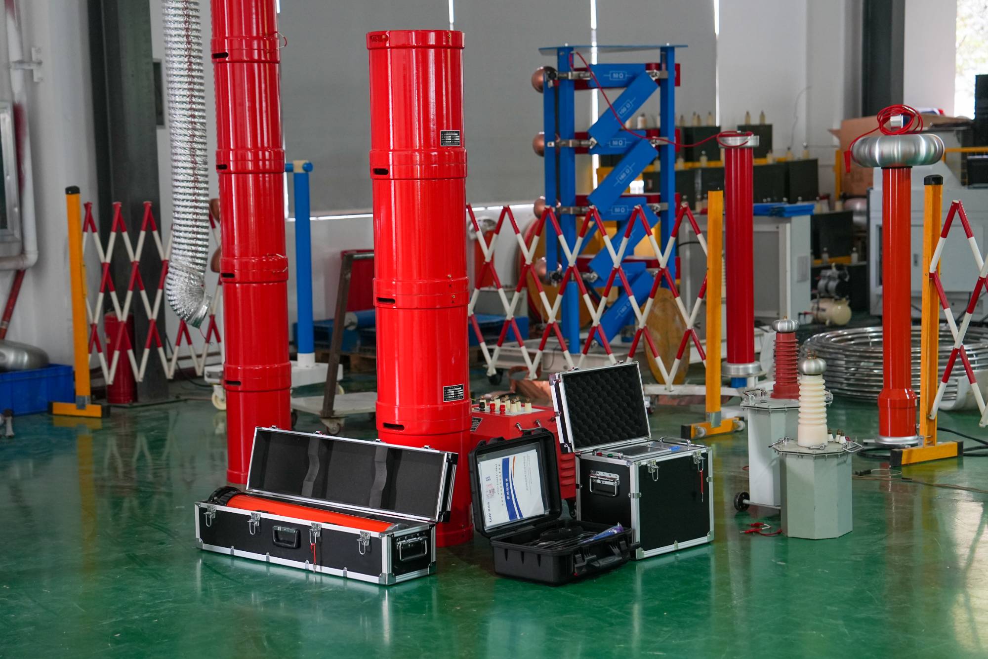
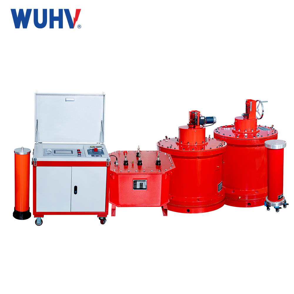
പരമ്പര അനുരണനംUHV പവറിന് കീഴിൽ, കൂടുതൽ സൗകര്യപ്രദമായി വിവിധ പവർ ടെസ്റ്റുകൾ നടത്താൻ നിരവധി പവർ തൊഴിലാളികളെ സഹായിക്കാൻ കഴിയും.
The frequency conversion resonance test device utilizes the principle of reactive power compensation, and only requires a small capacity and low voltage test power supply to successfully complete the withstand voltage test of generators, cables, and GIS composite electrical equipment. At the same time, the testing device can also be used for on-site testing of transformers, current transformers, voltage transformers, etc. This testing method is safe and reliable, and can effectively detect electrical equipment with insulation defects.
1. Principle of Frequency Conversion Resonance Test
The principle of frequency conversion resonance test is to use the equivalent capacitance of the combined equipment and a high-voltage reactor with known inductance to form a series circuit, and adjust the frequency of the test power supply through the frequency conversion power supply to achieve series resonance in the circuit. At this point, the reactive power of capacitors and reactors is balanced.
2. Components of frequency conversion resonance system
2.1 Control System
The control system is the heart module of the variable frequency resonance system, which includes all electronic and control modules. All modules are placed in a control cabinet, and the operation screen is located above the control cabinet. Operators can control all functions, read new measurement values (voltage, frequency, current, etc.), and observe the operating status of the system. The function of a three-phase bridge connected frequency converter is to convert the three-phase main power supply voltage into an adjustable amplitude square wave voltage, which is obtained through the main circuit switch and transmitted to a 6-pulse converter for rectification, and then provided to the capacitor bank. The square wave output voltage is generated by a conversion bridge at the desired output frequency, and the effective value of the output voltage is infinitely adjustable by adjusting the pulse width. All control signals are generated by the microprocessor, and the system generates a preset frequency or automatically adjusts the output frequency to the resonant frequency. The high-voltage system automatically tunes according to the operator's settings, controlling the boost, withstand time, and shutdown. It can also be connected to an external computer through the device's RS232 interface to control the entire system for automatic measurement.
2.2 Excitation Transformer
The function of the excitation transformer is to convert the output of the control unit into the input of the resonant circuit. The primary coil is connected to the control unit, while the secondary coil depends on the expected value of the quality factor of the high-voltage circuit. The excitation transformer can be made inside the reactor or as an independent unit.
2.3 High voltage reactor
At the resonant frequency, the reactor and load convert the excitation square wave voltage into an ideal sine wave. The parameter selection of high-voltage reactors must fully consider the power and frequency range of the test sample.
2.4 Multi level combination reactor
The combination of single-stage reactors can meet the optimal configuration of the circuit, ensuring the output voltage and frequency range. The voltage level of each stage reactor can be determined separately. The advantage of this type of reactor is that it is easy to combine and transport, but the disadvantage is that the operating time is short. Box type reactors are specially designed for on-site cable testing, and are oil immersed, naturally cooled reactors. Capacitive porcelain bushing output can be used, or cable terminal recharge SF6 output can be used. The standard output cable becomes the basic load of the system and is connected to the terminal of the cable under test.
2.5 Voltage measurement system, coupling capacitor, and basic load
The voltage measurement system includes a voltage divider and a peak voltage meter. The voltage meter is installed in the control cabinet and the voltage value is displayed on the operation screen. Voltage dividers can also be used as coupling capacitors and basic loads. In multi-stage combined reactors, the voltage divider is an independent unit, while in SF6 insulated and box type reactance systems, the voltage divider has already been installed in the reactor.
2.6 Experimental Parameters
The experimental parameters mainly include: ① Equivalent capacitance of the test sample C: This parameter mainly relies on accumulated experience or obtained through the manufacturer; ② The inductance L of the experimental reactor: The principle is to choose a resonant frequency between 30-300Hz; ③ The resonant frequency f of the circuit is calculated based on f=1/(2 π lc); ④ Test current I: calculated based on I=ω CU; ⑤ Test voltage U: The magnitude of the voltage value is determined specifically according to the test procedure.
3. Application and advantages of frequency conversion resonance system
3.1 Application
The application of frequency conversion resonance system is as follows: ① Voltage withstand test of GIS for Xin'an Transformer, Longgu Transformer, and Guantian Transformer; ② Voltage withstand test of main transformers in multiple substations including 110kV Xin'an Substation, Qili Substation, Fengcheng Substation, Luoshe Substation, Xishan Substation, Gaolin Substation, Qiancun Substation, Tangnan Substation, etc Voltage withstand test of 10kV cable with a length of 2 kilometers in Zhili; ④ Voltage withstand test of 35kV capacitor cables for Tangqiao and Changchao transformers; ⑤ A total of 12 cables for the main transformer of the Hengjie substation will be completed at once; ⑥ Qingshan 35kV voltage transformer withstand voltage.
3.2 Advantages
A large number of on-site tests have proven that the complete set of variable frequency series resonance test equipment can well meet the requirements of high-voltage systems for on-site testing, and has the following advantages:
(1) The small capacity of the experimental power supply reduces the constraints on on-site testing due to insufficient power capacity;
(2) The experimental device has a small volume, and the reactor adopts a multi-stage or stacked structure, which is convenient for transportation and on-site installation;
(3) The test wiring is convenient and the operation is simple, greatly reducing the test time;
(4) High safety and reliability, the IGBT and drive circuit used in the frequency converter have low waveform distortion and good frequency output stability;
(5) It has good IGBT, overcurrent, overvoltage, and discharge protection functions, which can protect equipment and personal safety. If breakdown occurs during the withstand voltage process, due to the loss of resonance conditions in the circuit, the output current of the power supply will automatically decrease, and the voltage at both ends of the test sample will suddenly drop, without generating overvoltage. The discharge energy is small, so it will not cause significant harm to the test device and the test sample;
(6) The equivalence of the experiment is good. An AC voltage close to the power frequency (30-300Hz) is used as the test power supply, which is very close to the 50Hz/60Hz power supply in terms of equivalence and consistency, thus ensuring the authenticity and reliability of the test results. Practice has proven that using a variable frequency series resonant system not only saves a lot of manpower and material resources, but also reduces testing time and system power outage time, improves power supply reliability, and achieves good economic and social benefits.


