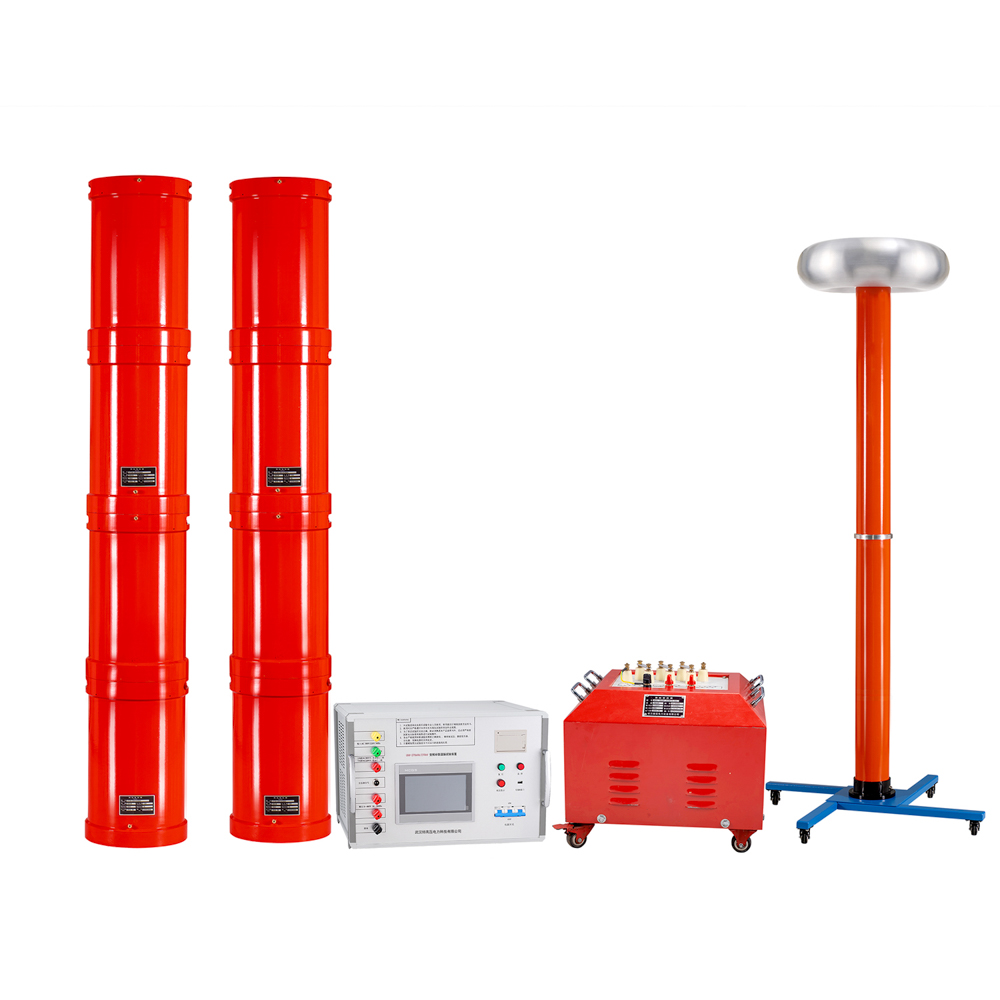
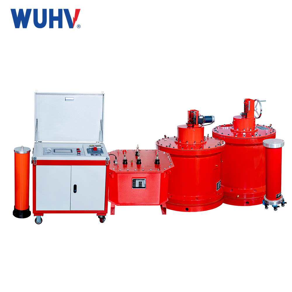
പരമ്പര അനുരണനംUHV പവറിന് കീഴിൽ, കൂടുതൽ സൗകര്യപ്രദമായി വിവിധ പവർ ടെസ്റ്റുകൾ നടത്താൻ നിരവധി പവർ തൊഴിലാളികളെ സഹായിക്കാൻ കഴിയും.

The reason why the resistance is not equal to the power supply voltage during resonance is that the voltage on the resistance during resonance is the sum of the power supply voltage and the voltage of the charging and discharging capacitors. So, resistance voltage=power supply voltage+capacitor voltage, not equal to power supply voltage. When a series resonant circuit resonates, the total impedance of the series resonant circuit is equal to the resistance, and the total resistance of the series resonant circuit is equal to the total voltage and the voltage across the resistance. At this time, there is voltage on both the capacitor and inductor, and the voltage on the inductor is equal to the voltage on the capacitor, but the voltage direction is opposite. Be careful when operating, and do not mistakenly believe that there is no voltage on capacitors and inductors, which may cause safety issues.
The frequency selection characteristics of a series resonant circuit are usually represented by the Q value, and the larger the Q value, the better the frequency selection characteristics. The total resistance of series resonance for a series circuit is Q=ω L/R=1/ω CR, therefore, the smaller the R=(external resistance+internal resistance), the better. For parallel circuits, the larger the R, the better. Of course, the issue of maximum power output also needs to be considered, so generally, the internal resistance of series resonance is equal to the external resistance of series resonance. If the signal source is constant and the external resistance is constant, it is necessary to adjust the external capacitance and inductance appropriately to increase the frequency selection characteristics of the circuit. Why is the voltage on the resistor lower than the voltage on the signal source when a series resonance experiment occurs in the circuit. The current is the same everywhere in a series circuit. This is the same, not only the effective value is the same, but also the instantaneous value is the same, that is to say, it is the same at any time.
The current in inductors and capacitors is different from the voltage at both ends. The voltage at both ends of the capacitor lags behind the current by 90 degrees, while the voltage at both ends of the inductor leads the current by 90 degrees. Nowadays, the current phase in inductors and capacitors is the same, so the voltage across the inductor is opposite in phase to the voltage across the capacitor. In other words, at any time, the voltage across the capacitor and inductor cancels each other out. Series resonance refers to the fact that both the inductive and capacitive reactance are frequency dependent, and there must exist a certain frequency at which the inductive and capacitive reactance are equal. Since the voltage across the inductor is the product of inductance and current, and the voltage across the capacitor is the product of capacitance and current, at this frequency, the voltage across the inductor is exactly equal in magnitude and opposite in direction to the voltage across the capacitor, completely canceling each other out. In an AC circuit with resistor R, inductor L, and capacitor C components, the voltage at both ends of the circuit is generally different in phase from the current in it. If the parameters or power frequency of circuit components (L or C) are adjusted, they can be made to have the same phase, and the entire circuit appears purely resistive. When a circuit reaches this state, it is called resonance.
The total resistance of series resonance is in a series circuit composed of resistance, inductance, and capacitance. When the capacitance reactance XC is equal to the inductance reactance XL, i.e. XC=XL, the phase of the voltage U and current I in the circuit are the same, and the circuit exhibits pure resistance. This phenomenon is called series resonance. When a series resonance occurs in a circuit, the impedance of the circuit is Z=√ R2+XC, and the voltage on the reactive element is the highest, so it is also called voltage resonance; Many places in life are designed using the principle of series resonance, where the capacitor and reactor of the test object form a series resonance connection. The resonant voltage of the voltage divider is used as an overvoltage protection signal, and the frequency modulation power output is excited by the coupling resonance excitation power.
In a series circuit, there are two methods to measure the quality factor Q of the total resistance circuit in series resonance. One is to determine it according to the formula Q=UL/U0=Uc/U0, where Uc and UL are the voltages on capacitor C and inductor L at resonance, respectively; Another method is to measure the passband width △ f=f2-f1 of the resonance curve, and then calculate the Q value based on Q=f0/(f2-f1). In the formula, f0 is the resonant frequency, and f2 and f1 are the upper and lower frequency points when the amplitude of the output voltage drops to 1/√ 2 (=0.707) times the maximum value due to detuning. The larger the Q value, the sharper the curve, the narrower the passband, and the better the selectivity of the circuit. When powered by a constant voltage source, the quality factor, selectivity, and passband of the circuit are only determined by the parameters of the circuit itself and are independent of the signal source. Series resonance refers to the phenomenon where the excitation voltage source is applied at a certain frequency to the two ends of a circuit consisting of a series resonant resistor, capacitor, and inductor (any actual circuit can be equivalent to this Thevenin circuit model), and the total inductance is zero. At this point, the excitation source is directly applied to the resistor, and the ratio of the total inductance or capacitance to the resistance in the circuit is the quality factor of series resonance. However, the quality factor cannot be less than zero. If it is less than zero, the circuit will experience self-excited oscillation.


