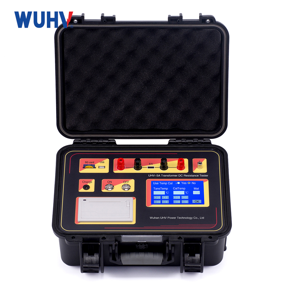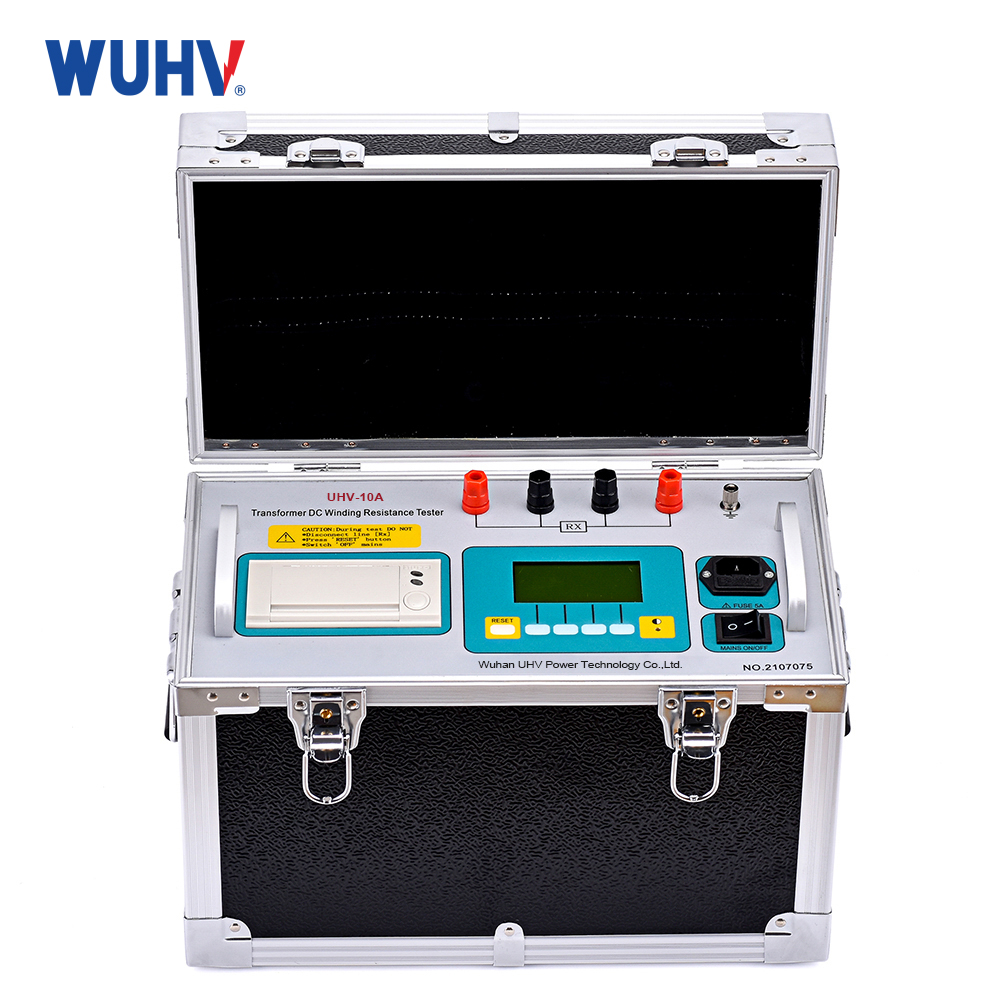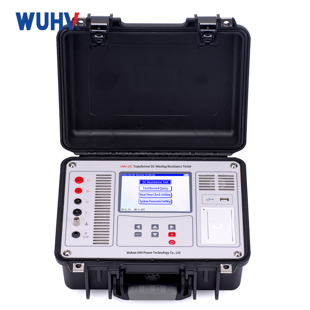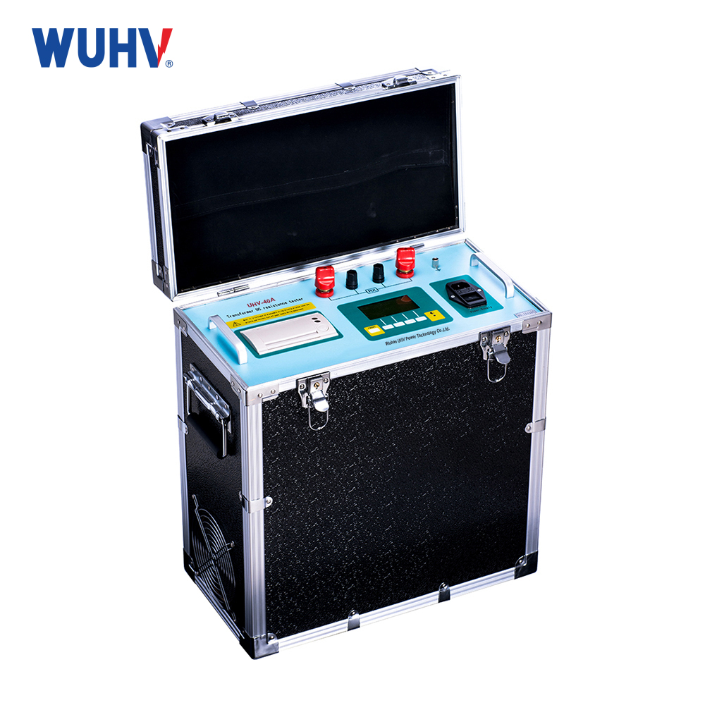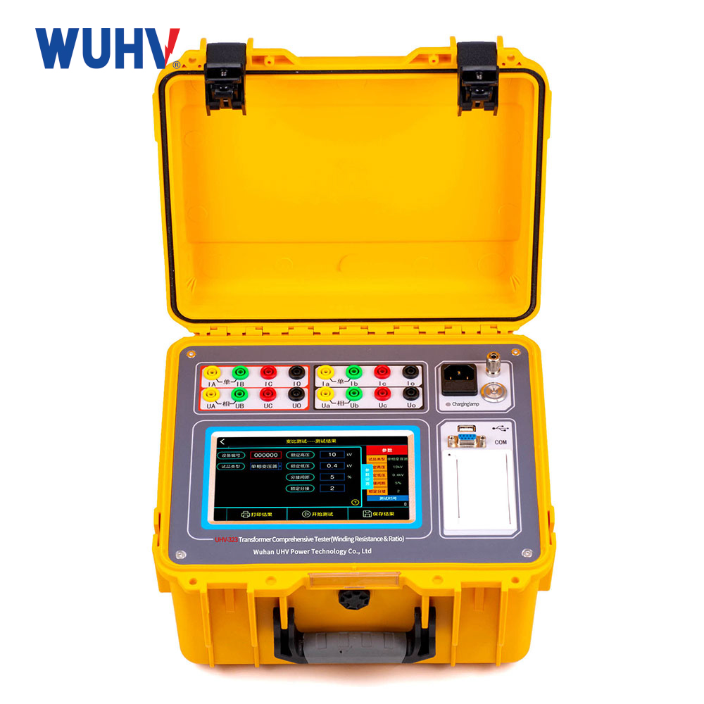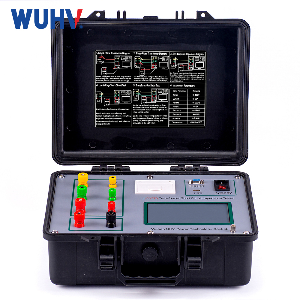
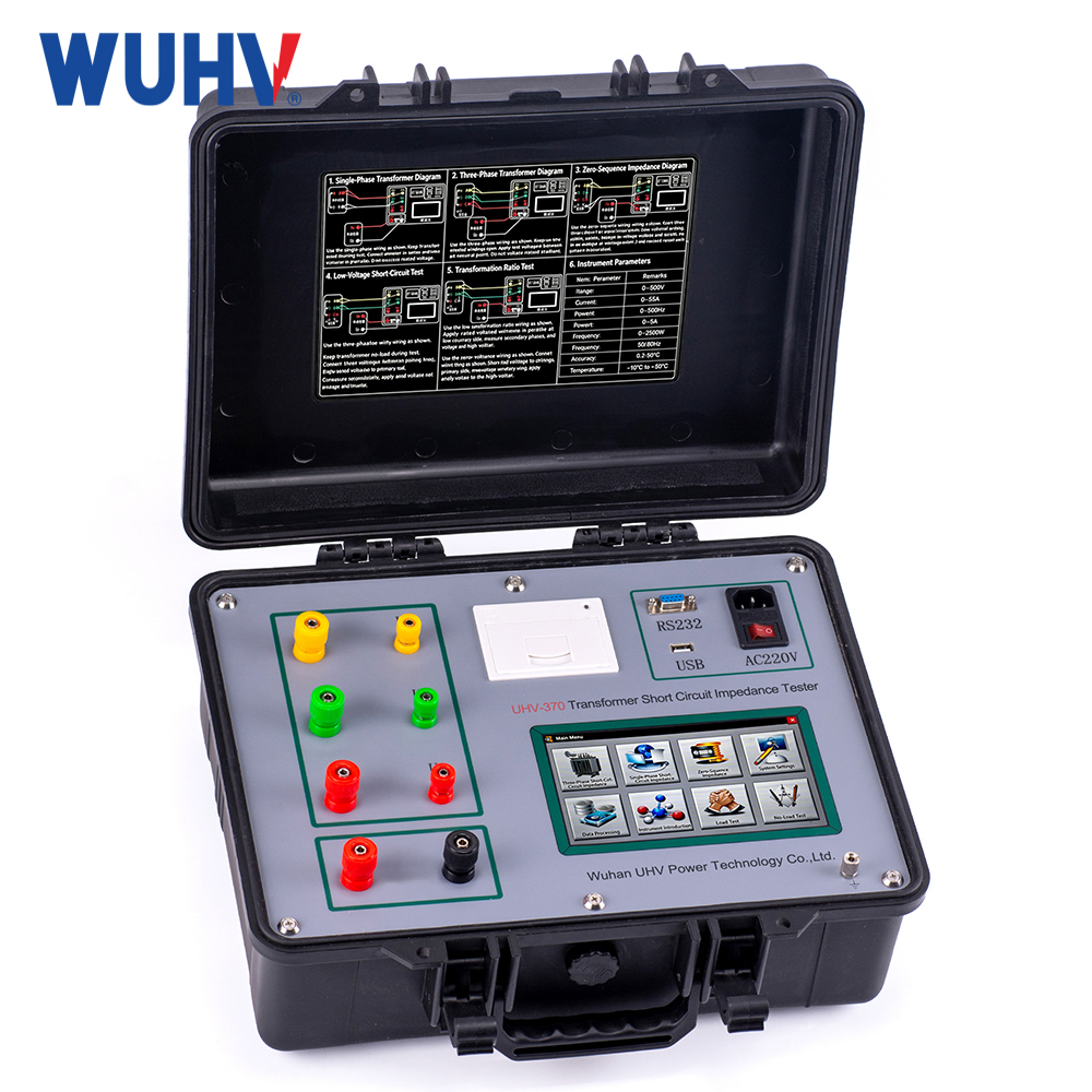
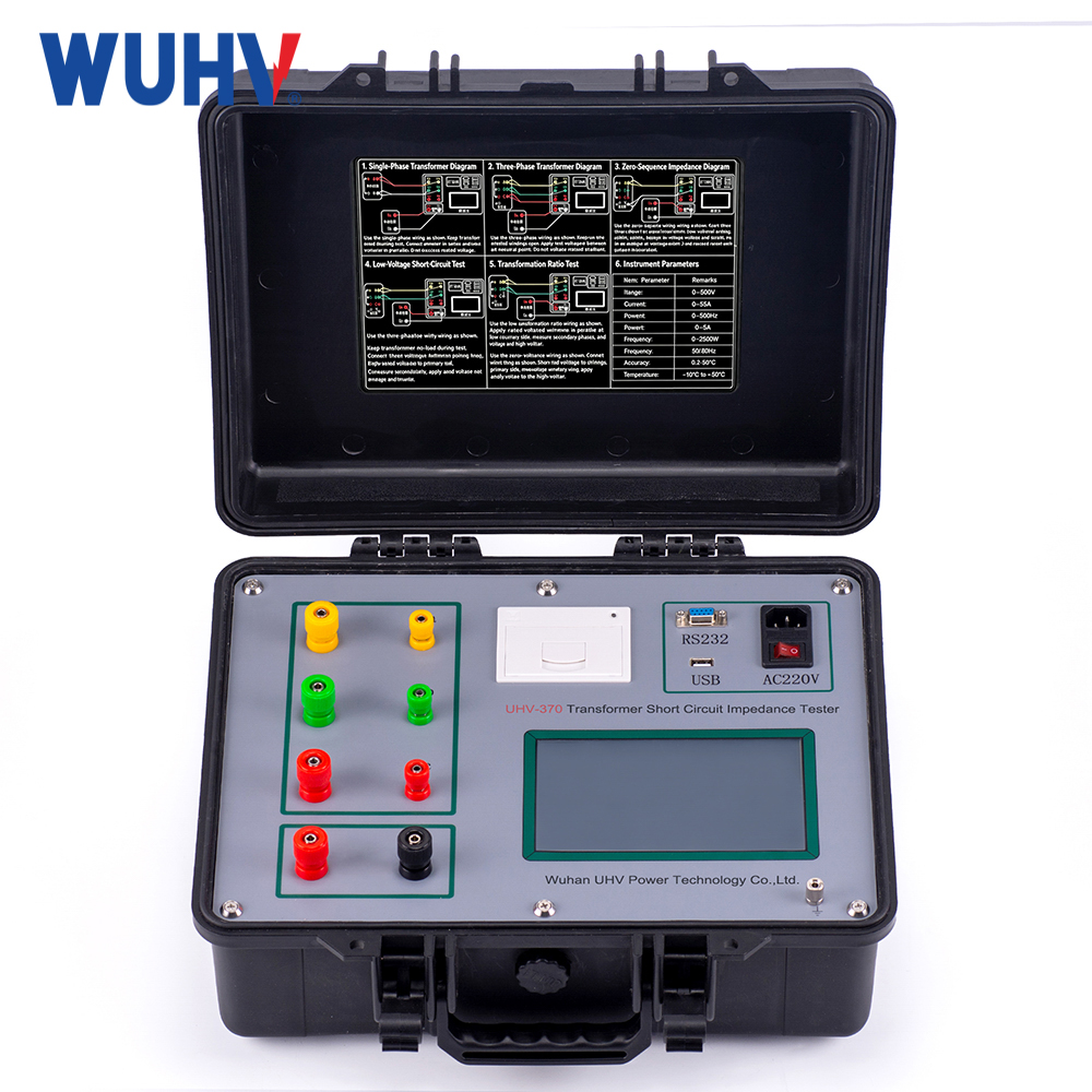
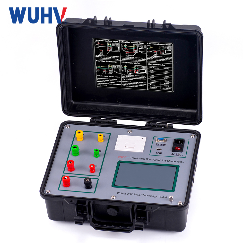
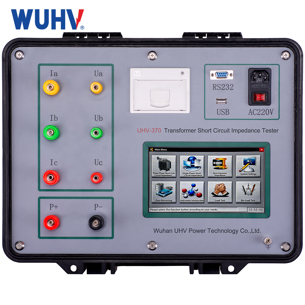


Product Introduction:
The low-voltage short-circuit impedance test is the most direct way to verify whether a transformer's windings are deformed due to mechanical impact during transportation or installation, or short-circuit current shock during operation. It is crucial for determining whether a transformer is operational and serves as a basis for determining whether to disassemble the transformer for inspection.
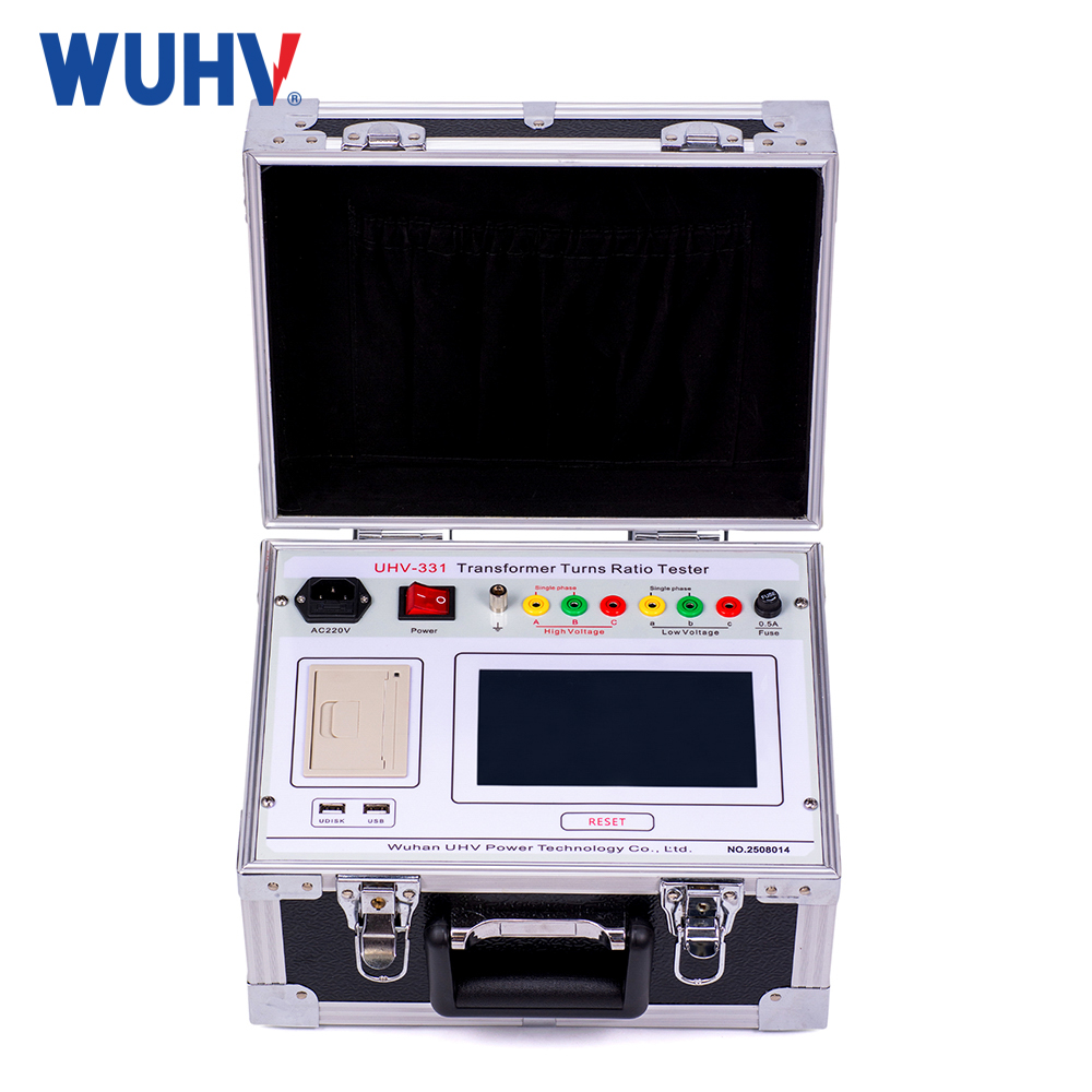
The low-voltage short-circuit impedance tester is suitable for low-voltage impedance testing of power transformers (single-phase or three-phase) during factory delivery, handover, pre-testing, and overhaul. It is a rapid tester for verifying transformer winding deformation.
Product functions:
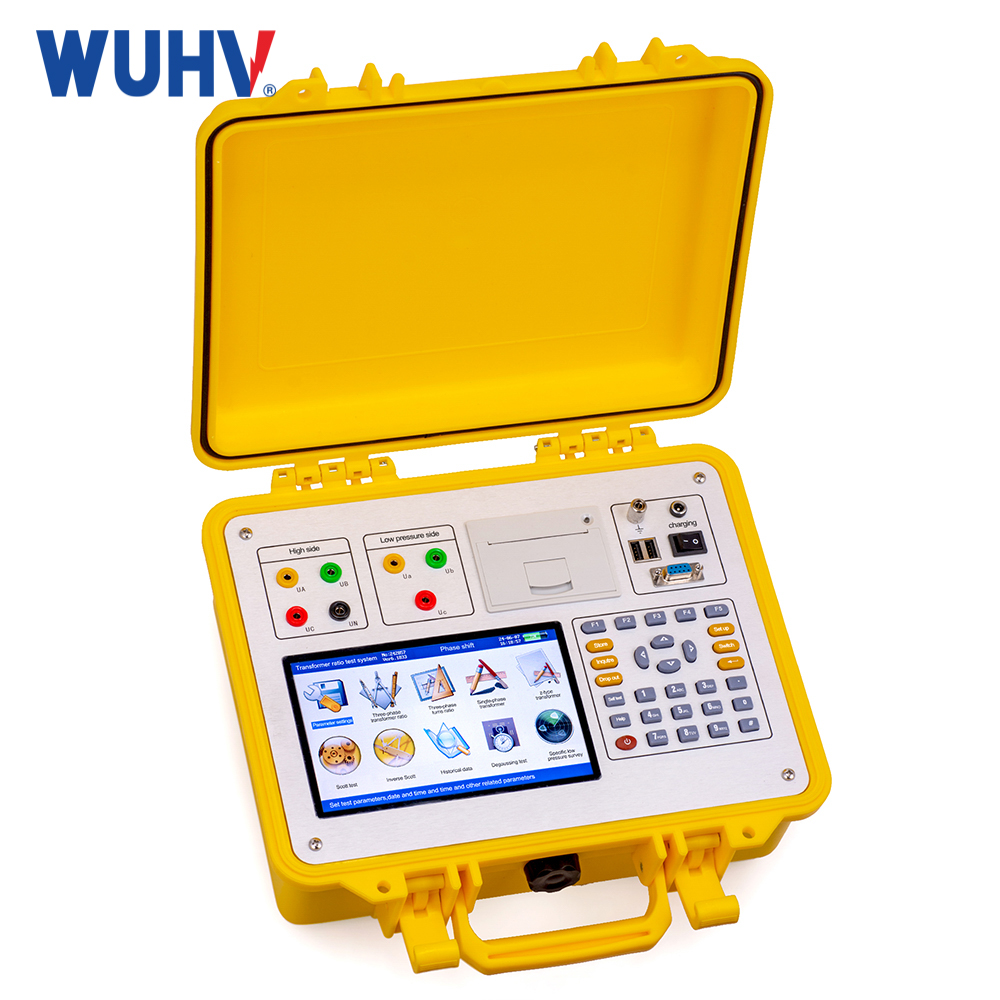
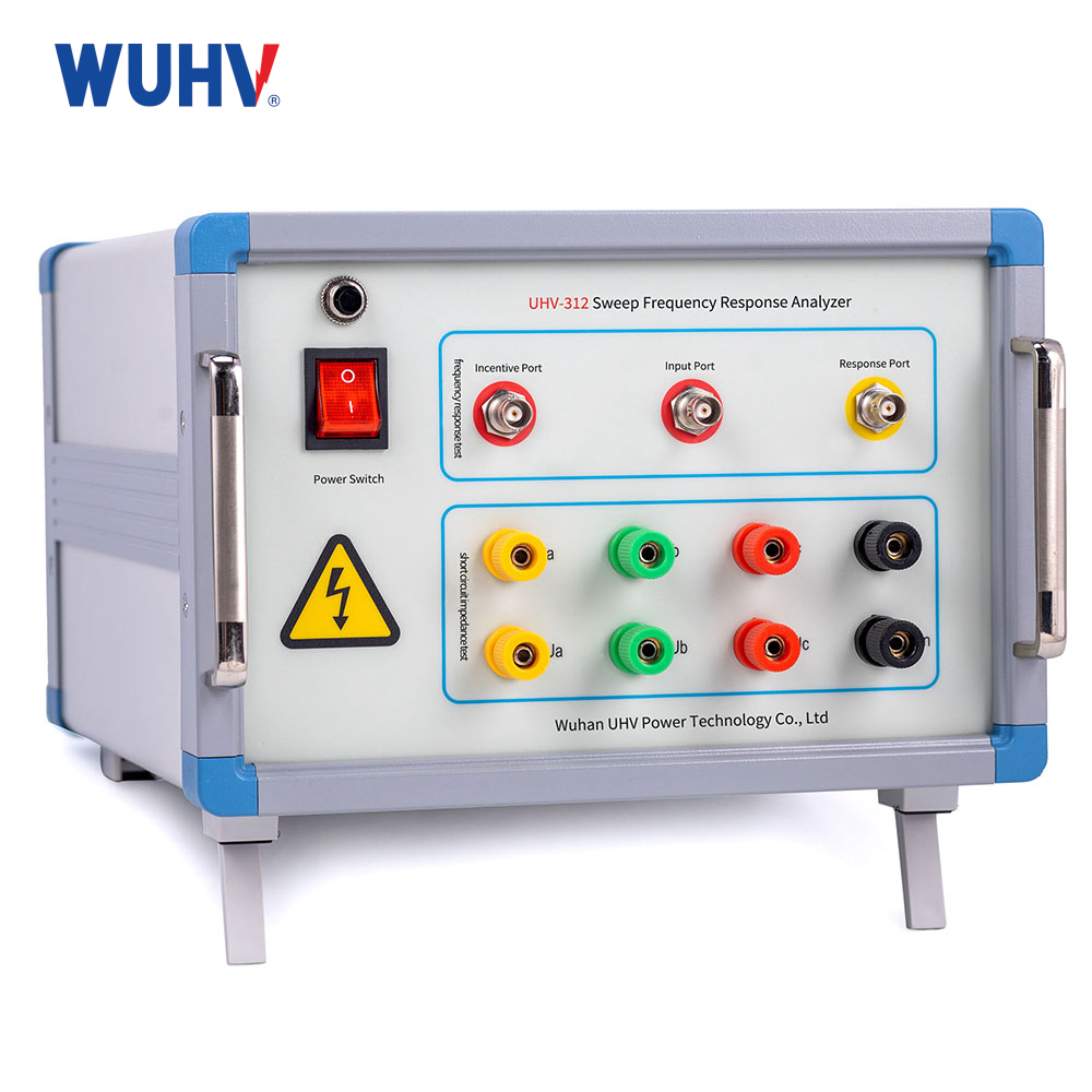
The transformer short-circuit impedance tester manufactures is a specialized device used for inspecting the mechanical condition and electrical performance of power transformer windings. It is primarily used to measure parameters such as short-circuit impedance and load losses. By comparing the measured values with factory or historical data, it can determine whether the windings have experienced deformation, displacement, or loosening due to short-circuit impacts, transportation vibration, or mechanical stress. The instrument features high measurement accuracy, fast testing speed, automatic calculation and analysis, data storage and export, and strong anti-interference capability. It is widely used in transformer factory testing, acceptance testing, preventive testing, and fault diagnosis, providing a reliable basis for the safe operation and condition-based maintenance of transformers.
Technical parameters:
| വോൾട്ടേജ് പരിധി | 15V~500V(PT expansion available), accuracy: ±(reading × 0.2% + 0.05%(range)) |
| Current range | 0.5A~15A(Internal), accuracy: ±(reading × 0.2% + 0.05%(range)) |
| 0.5A~50A(External)(CT expansion available), accuracy: ±(reading × 0.2% + 0.05% (range)) | |
| Impedance range | 0~100% |
| പവർ ഫാക്ടർ | 0.02 < cosΦ < 0.1, Accuracy: ±(reading × 1.0% + 0.05% (range)) |
| cosΦ ≥ 0.1, Accuracy: ±(reading × 0.5% + 0.05% (range)) | |
| Frequency measurement | 45~65Hz |
| റെസലൂഷൻ | 5 significant digits |
| Main host size | 405×330×180(mm) |
| Host weight | 9.5kg |
| ഉപയോഗ വ്യവസ്ഥകൾ | |
| ആംബിയന്റ് താപനില | -10℃~50℃ |
| അന്തരീക്ഷ ഈർപ്പം | ≤85%RH |
| വൈദ്യുതി വിതരണം | AC220V ±10% |
Product Features:
1. The instrument measures single-phase impedance, three-phase impedance, zero-sequence impedance (star with neutral point), and both no-load and load measurements.
2. The instrument has two power supply modes: internal power and external single-phase voltage regulator.
3. The instrument offers wide voltage and current measurement ranges and high accuracy.
4. 7.0-inch touch screen for easy operation.
5. Built-in large-capacity non-volatile memory capable of storing 160 sets of data.
6. Built-in high-speed micro thermal printer for printing measurement data.
7. Built-in high-precision clock for real-time time display.
8. USB flash drive storage.
Application Scenarios
Acceptance and preventive testing (factory / arrival / annual inspection): This is the most routine application. New transformers must undergo this test after factory production, installation, or major overhaul, and the measured data serve as the original "fingerprint" record. During subsequent regular annual inspections, deviations between current values and initial values help determine whether subtle changes have occurred inside the transformer. This is a core method of predictive maintenance in power systems.
2. Post-fault diagnosis of transformers (emergency response): When a transformer trips due to lightning strikes, external short circuits, or overload, the instrument is used immediately on site. Typically within just a few tens of minutes, it can quickly determine whether the windings have suffered severe deformation, enabling a decision on whether the transformer "needs to be returned to the factory for major repair" or "can continue trial operation." This saves critical time for emergency power restoration and avoids secondary equipment damage caused by blind energization.
3. Condition verification after transportation or installation (logistics stage): During long-distance transport or on-site hoisting, large transformers may experience internal support loosening due to jolting or impact. Before formal commissioning and after the transformer is in place, a short-circuit impedance test is conducted as a "shipping insurance" verification to ensure the internal structure has not been damaged during logistics.
4. Specialized winding deformation diagnosis (in-depth inspection): This is the most irreplaceable function of the instrument. For transformers with long service life or those that have experienced multiple short-circuit impacts, the test can detect slight axial or radial distortion in the windings. Particularly under low-voltage, high-current test conditions, it can sensitively capture impedance differences caused by inter-disc capacitance changes, proving more effective than measuring DC resistance alone.
5. Three-phase asymmetry and tap changer testing (fine adjustment): By separately testing the three-phase impedance on both the high-voltage and low-voltage sides, it is possible to determine whether there is asymmetry or inter-turn short circuits in the three-phase windings. In addition, when adjusting the tap changer, testing impedance values at different tap positions can verify the contact condition and proper operation of the tap changer.
FAQ about Transformer Short Circuit Impedance Tester
What is a transformer short-circuit impedance tester, and why is it needed?
Transformer short-circuit impedance tester manufactures is a specialized testing device used to measure key parameters such as short-circuit impedance and load losses of transformers. By analyzing the test results, it can determine whether abnormalities have occurred in the windings and internal mechanical structure. Compared with traditional testing methods, it offers higher testing efficiency and better measurement accuracy, and can provide a reliable basis for transformer condition assessment and fault diagnosis without the need to disassemble the equipment.
How can the accuracy of transformer short-circuit impedance testing be improved?
To ensure the reliability of test data, it is important to verify that the tester has been properly calibrated, that the test circuit is correctly connected, and that the test method is selected to match the transformer parameters. In addition, strong electromagnetic interference on site should be avoided, and test conditions should be kept consistent across different tests to ensure good comparability of data over time.
What factors should be considered when selecting a transformer short-circuit impedance tester?
When selecting a model, comprehensive consideration should be given to factors such as test voltage level, applicable transformer capacity, measurement accuracy, test range, and data processing capabilities. At the same time, attention should also be paid to whether the device supports automatic testing, multi-tap measurement, data storage and export, temperature correction, and anti-interference capabilities, in order to meet different on-site environments and long-term usage requirements.